FAQ
Pytania dotyczące instalacji sterownika
Pytania dotyczące algorytmu pracy sterownika
Pytania dotyczące obsługi sterownika z panela
Pytania dotyczące oprogramowania na komputer PC
Pytania dotyczące obsługi sterownika ze strony WWW
Odpowiedzi
Pytania ogólne
Sterownik bruli.pl można zakupić u naszych partnerów - zakładka SKLEP
Powodów jest kilka. Pierwszy i najważniejszy, to obawa przed niewłaściwym użyciem eCoal.pl wynikająca z braku doświadczenia przy montażu i uruchomieniu kotła - głównie chodzi tu o doświadczenie i znajomość instalacji centralnego ogrzewania.
Sterowniki oferujemy tylko firmom kotlarskim, którym rekomendacje wystawia Instytut Chemicznej Przeróbki Węgla.
Proszę odwiedzać portal kotły co – poradnik użytkownika gdzie pojawiają się rzetelne informacje o kotłach na paliwa stałe.
Możliwe rozwiązanie to dodawanie paliwa o niskiej liczbie ROGI - tak powstają paliwa kwalifikowane - lub biopaliw typu owies, żyto, wióry itp. Proszę zwrócić uwagę, że nawet obecność w popiele żużlu nie wpływa znacząco na sprawność kotła. Koks można dopalić przez duże nadmiary powietrza - co czynią użytkownicy w trybie ustawiania spalania ręcznie i bez kontroli temperatury spalin wywołując potężną stratę kominową.
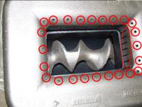
Bezwzględnie należy również sprawdzić szczelność korony palnika. Korona powinna zostać wklejona na silikon wysokotemperaturowy (1200 deg). Jeśli palnik posiada otwory powietrza wtórnego należy je bezwzględnie zakleić silikonem wysokotemperaturowym (otwory do zaklejenia zaznaczono na czerwono):
Jeśli powyższe metody są niemożliwe do zrealizowania, należy obniżyć maksymalnie temperaturę zadaną CO na kotle oraz aktywować regulator pokojowy. Do poprawnej pracy regulatora pokojowego wymagany jest czujnik temperatury wewnętrznej, który jest w zestawie razem ze sterownikiem. Czujnik temperatury wewnętrznej należy zamontować w pomieszczeniu, w którym chcemy kontrolować temperaturę. Należy również aktywować cykliczną pracę pompy CO (Ustawienia zaawansowane - kod PIN: 7492). Czas pracy/postoju pompy CO należy dobrać eksperymentalnie, analizując zachowanie temperatury wewnętrznej.
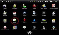
1. Po wejściu do menu uruchamiamy aplikację Market:
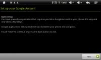
2. Klikamy przycisk Next:
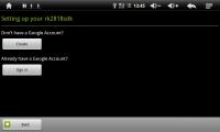
3. Aby rozpocząć procedurę utworzenia nowego konta klikamy przycisk Create
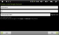
4. W kolejnych polach podajemy: Imię, Nazwisko, Login. Klikamy następnie przycisk Next. Jeśli login będzie już zajęty zostaniemy o tym poinformowani. Wtedy należy wybrać inny login.
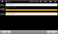
5. W kolejnym oknie musimy podać hasło i powtórzyć je w drugim polu. Po podaniu haseł klikamy Next. Należy użyć silnego hasła - pasek Password strength zostanie wypełniony kolorem. W przypadku użycia zbyt słabego hasła serwis poprosi na o podanie mocniejszego.
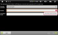
6. Następnie należy odpowiedzieć na proste pytanie lub podać dodatkowy adres email. Procedura ta służy do późniejszej weryfikacji użytkownika w przypadku zagubienia hasła. Klikamy następnie przycisk Create
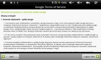
7. W kolejnym oknie akceptujemy warunki korzystania z Serwisów spółki Google - klikamy przycisk I agree, Next
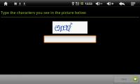
8. Ostatni krok to potwierdzenie i weryfikacja wprowadzonych danych. Należy przepisać kod z obrazka i kliknąć przycisk Next
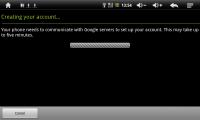
9. Kolejne okno informuje o przesyłaniu danych na serwery Googla - tworzenie konta użytkownika:
10. Proces tworzenia konta został zakończony. Można teraz uruchomić aplikację Android Market i rozpocząć proces instalacji aplikacji. Pierwsze uruchomienie usługi Android Market będzie wymagało akceptacji regulaminu - należy kliknąć przycisk I agree, next

Mając już ustanowione połączenie w systemie Android uruchamiamy aplikację eSterownik Mobile klikając na ikonkę:
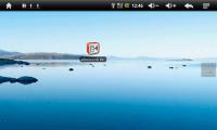
Po uruchomieniu aplikacji powinien się pojawić mniej więcej taki ekran jak poniżej:
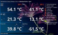
Wybieramy MENU (w tabletach leader R70 należy kliknąć w lewy przycisk u góry obudowy) i klikamy konfiguracja. Poniżej wygląd menu z konfiguracją programu:
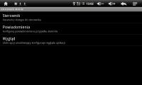
Klikamy na pole Sterownik (Parametry dostępu do sterownika) - przejdziemy do kolejnego menu:
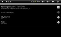
Aby nawiązać komunikację ze sterownikiem, który jest w lokalnej sieci Ethernet pole Sposób podłączenia sterownika powinno być odznaczone - będzie aktywne pole Adres sterownika.
W polu Adres sterownika podajemy adres IP sterownika, a w polach Użytkownik i Hasło podajemy Login i hasło dla użytkownika z pełnym dostępem (domyślnie: admin:admin).
Konfiguracja jest już zakończona. Można opuścić menu i powrócić do głównego ekranu. W tym momencie, jeśli adres IP oraz dane logowania są poprawne zostanie nawiązane połączenie ze sterownikiem, a temperatury będą odświeżane on-line.
Mając już ustanowione połączenie w systemie Android uruchamiamy aplikację eSterownik Mobile klikając na ikonkę:

Po uruchomieniu aplikacji powinien się pojawić mniej więcej taki ekran jak poniżej:

Wybieramy MENU (w tabletach leader R70 należy kliknąć w lewy przycisk u góry obudowy) i klikamy konfiguracja. Poniżej wygląd menu z konfiguracją programu:

Klikamy na pole Sterownik (Parametry dostępu do sterownika) - przejdziemy do kolejnego menu:

Aby nawiązać komunikację ze sterownikiem, który jest podłączony do platformy eSterownik.pl pole Sposób podłączenia sterownika powinno być zaznaczone - pole Adres sterownika będzie nieaktywne.
Jeśli nie posiadamy konta na portalu eSterownik.pl a chemy mieć dostęp do publicznych sterowników, pole Użytkownik oraz Hasło należy pozostawić puste.
Jeśli posiadamy konto na eSterownik.pl należy w polu Użytkownik oraz Hasło podać dane go logowania na portal.
Konfiguracja jest już zakończona. Można opuścić menu i powrócić do głównego ekranu. Należy jeszcze wybrać, do którego sterownika chcemy się podłączyć. W tym celu klikamy przycisk Menu i wybieramy pole Wybierz sterownik. Na ekranie zobaczymy listę sterowników dostępną na platformie eSterownik.pl:
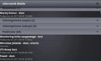
Należy wskazać interesujący nas sterownik. Automatycznie zostaniemy przeniesieni do głównego okna.
Dowodem na połączenie szyfrowane jest adres strony, który zaczyna się od "https://..." zamiast "http://..."
Posiadamy Certyfikat SSL wystawiony przez Unizeto Technologies S.A. który potwierdza, że zapewniamy podczas połączenia z naszymi serwerami:
- bezpieczeństwo – szyfrowanie połączeń, bezpieczne przekazywanie danych,
- wiarygodność – potwierdzenie tożsamości strony WWW w internecie,
- zaufanie – świadczenie usług zgodnie ze światowymi standardami.
Wszystkie hasła użytkowników platformy eSterownik.pl zapisane są w bazie danych po przekształceniu przez algorytmy oparte o jednokierunkowe kryptograficzne funkcje skrótu. Oznacza to, że nikt nie ma dostępu do haseł użytkownika (nawet administratorzy platformy eSterownik.pl).
Każda transakcja wymiany danych sterownika eCoal.pl/bruli.pl z serwerem eSterownik.pl zabezpieczona jest losowym loginem i hasłem, które generowane są przy każdym nawiązaniu połączenia.
eSterownik Mobile na system Android również korzysta z zabezpieczonego protokołu SSL i nie posługuje się otwartymi hasłami a jedynie ich „hashami”.
* na liście urządzeń klikamy ikonę Modyfikuj
* klikamy przycisk Dodaj Powiadomienia
* podajemy numer telefonu oraz wybieramy alarmy które mają być wysyłane SMS
* na liście urządzeń klikamy ikonę Przejdź do urządzenia
* na nowo otwartej stronie wybieramy z lewego menu zakładkę Powiadomienia
* klikamy przycisk Dodaj rekord
* podajemy numer telefonu oraz wybieramy alarmy które mają być wysyłane SMS
Pytania dotyczące instalacji sterownika
Na karcie SD rejestrowane są następujące parametry pracy sterowników eCoal.pl/bruli.pl:
- archiwum wszystkich mierzonych temperatur z czujników pomiarowych (z krokiem 60 sek)
- temperatura zadana CO oraz temperatura zadana CWU
- wystąpienia i ustąpienia alarmów
- zmiana trybu pracy sterownika
- załączenie/wyłączenie sterownika
- obciążenie łącza internetowego w sterowniku
- statystyka odwiedzin
Wszystkie zarejestrowane zdarzenia można wyświetlić bezpośrednio w przeglądarce internetowej
Sterowniki obsługują wszystkie karty Secure Digital - SD (format 24mm/32mm).
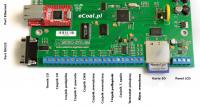
Połączenie przez RS-232 jest wymagane aby zaktualizować oprogramowanie w sterowniku. Jeżeli w komputerze nie ma portu RS-232, to można dokupić konwerter USB-RS232 - polecamy konwertery firmy DIGITUS. Konwerter taki podłączamy do portu USB. Porty USB są dostępne praktycznie w każdym komputerze.
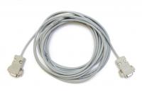
Kabel łączący sterownik z komputerem powinien zostać dostarczony razem ze sterownikiem.
Jeśli wymagane jest przedłużenie lub wykonanie kabla we własnym zakresie poniżej zamieszczamy schemat.

Należy zastosować półprzewodnikowy czujnik temperatury typu KTY81-210 i
podłączyć go przewodem dwużyłowym o przekroju nie mniejszym niż 0,25 mm2 do zacisków na listwie w skrzynce sterowniczej oznaczonych "T.WEW".
Czujnik temperatury spalin jest typu Pt-100 a wszystkie pozostałe czujniki temperatury są typu KTY81-210. Oznacza to możliwość wykorzystywania czujników KTY81-210 zamiennie czyli dowolny czujnik temperatury typu KTY81-210 podłączony do zacisków "T.WEW" i będzie spełniał funkcję czujnika temperatury wewnętrznej.
Zachęcamy wszystkich użytkowników sterownika eCoal.pl/bruli.pl do podłączania czujnika temperatury wewnętrznej, gdyż pozwala to dokonywać oceny skuteczności regulacji temperatury za niewielkie pieniądze - cena czujnika to zaledwie kilka złotych, a forma jego montażu czyli obudowa może być dowolna ale zalecamy żeby wybór zatwierdzały żony.
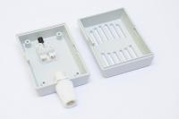
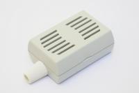
Czujnik KTY81-210 w obudowie:
Czujniki temperatury należy instalować zgodnie z poniższym rysunkiem.

Zainstalowane czujniki temperatury wewnętrznej jak i zewnętrznej zapewnią rejestrację tych pomiarów na karcie pamięci. A dokładna analiza wykresów pozwoli Państwu lepiej zarządzać energią cieplną wytworzoną przez kocioł.
Dodatkowo czujnik temperatury zewnętrznej umożliwia korzystanie z regulatora pogodowego, a czujnik temperatury wewnętrznej umożliwi korzystanie z regulatora pokojowego.
Sterownik eCoal.pl/bruli.pl obsługuje czujniki temperatury typu KTY81-210.
Poniżej czujnik temperatury KTY81-210 w obudowie.

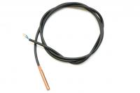
Sterownik eCoal.pl/bruli.pl obsługuje czujniki typu KTY81-210 oraz PT100 (temperatura spalin). W ofercie dostępne są czujniki w różnym wykonaniu:
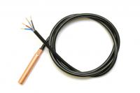
Czujnik temperatury CO z wbudowanym zabezpieczeniem termicznym (KTY81-210)
Czujnik temperatury podajnika (KTY81-210)
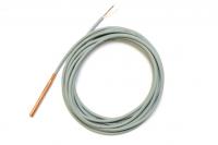
Czujnik temperatury CWU (KTY81-210)

Czujnik temperatury wewnętrznej/zewnętrznej (KTY81-210)
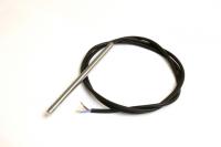
Czujnik temperatury spalin (PT100)

Pytania dotyczące algorytmu pracy sterownika
Przyczyny wygaszania kotła:
1. Wskazywanie zbyt niskiej temperatury spalin - poniżej 70 stopni - sterownik widzi to jako brak spalania:
- oklejony czujnik sadzami - czyścić okresowo czujnik spalin przez wysunięcie go z czopucha i ponownie wsunięcie
- koniec czujnika nie znajduje się w strumieniu spalin przez zbyt głębokie lub zbyt płytkie wsunięcie - skorygować położenie; czujnik powinien znajdować się w środku czopucha lub nieco płycej
- zasypany popiołem koniec czujnika - wyczyścić czopuch
- niewłaściwa kalibracja czujnika spalin - dokonać ponownej kalibracji w ustawieniach zaawansowanych
2. Wskazywanie zbyt wysokiej temperatury spalin - powyżej 400 stopni - uszkodzony czujnik spalin - wymienić czujnik.
- Wybór AutoLato-temp. umożliwia włączenie funkcji, która automatycznie powyżej ustalonej temperatury zewnętrznej aktywuje w sterowniku tryb Lato. Funkcja ta służy do przełączenia instalacji z trybu normalnego (grzanie obwodu CO) w tryb letni – praca tylko układu CWU.
- Wybór AutoLato-prog. przełącza tryb Lato/Normalny wg. zdefiniowanych okresów czasowych w programatorze AutoLato-prog
Wbudowany programator pokojowy posiada taką samą funkcjonalność jak zewnętrzny termostat pokojowy. Użytkownik ma możliwość zdefiniowana temperatury dziennej (wyższej) oraz nocnej (niższej), która będzie utrzymywana w pomieszczeniu reprezentacyjnym. Do działania programatora pokojowego niezbędny jest czujnik temperatury wewnętrznej zainstalowany w pomieszczeniu.
Działanie układu:
- Jeśli temperatura w pomieszczeniu jest niższa niż zadana, na kotle ustalona jest temperatura normalna (komfortowa).
- Jeśli temperatura w pomieszczeniu wzrośnie powyżej zadanej, na kotle ustalona jest temperatura obniżona.
W przypadku, gdy obniżenie temperatury zadanej CO powoduje przegrzewanie pomieszczeń należy zastosować pracę cykliczną pompy CO (par. zaawansowane - Tryb pracy pompy CO).
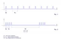
Histogram (cyt. Wikipedia) to jeden z graficznych sposobów przedstawiania rozkładu empirycznego cechy. Składa się z szeregu prostokątów umieszczonych na osi współrzędnych. Prostokąty te są z jednej strony wyznaczone przez przedziały klasowe (patrz: Szereg rozdzielczy) wartości cechy, natomiast ich wysokość jest określona przez liczebności.
W naszym przypadku na osi X zgrupowane są czasy postoju podajnika o rozdzielczości 10 sek. Im wyższy słupek, tym więcej razy wystąpił określony czas postoju. Z lewej strony histogramu mamy krótsze czasy postoju zaś z prawej strony czasy dłuższe.
Czasy postoju są zależne od intensywności pracy dmuchawy – im wyższe obroty dmuchawy - tym proces spalania jest szybszy, im niższe obroty dmuchawy – tym proces spalania jest wolniejszy.
Czas postoju nie może być za krótki – zbyt intensywne spalanie (lewa strona histogramu) oraz zbyt długi – zbyt wolne spalanie (prawa strona histogramu).Rozłożenie słupków na histogramie dokumentuje działanie algorytmu spalania grupowego. Jeśli wysokie słupki pojawią się przyklejone do prawej strony histogramu świadczy to o tym, że algorytm nie wykrywa w założonym czasie dopalenia paliwa - świadczy to o zbyt małym nadmuchu.
Podane informacje mają pomóc w ustawieniu mocy dmuchawy w procesie spalania grupowego.

Pytania dotyczące obsługi sterownika z panela
Strzałka skierowana w dół przy temperaturze zadanej CO lub CWU oznacza, że temperatura została obniżona o zadaną wartość ustaloną w parametrach użytkownika. Wynikać może to z kilku powodów:
- rozwarty styk termostatu pokojowego przy aktywnym zadawaniu: Termostat
- zdefiniowana temperatura obniżona w programatorze CO, CWU lub pogodowym
- przekroczenie temperatury wewnętrznej przy aktywnym zadawaniu z programatora pokojowego
Litery wyświetlane po prawej stronie wyświetlacza LCD wskazują tryb pracy sterownika.
W pierwszej linii wyświetlane jest (kolejno od lewej strony) status układu CO:
- CO - informacja dotyczy układu CO
- XX.X - aktualna temperatura wody wychodzącej z kotła (temp. CO)
- XX - temperatura zadana wody wychodzącej z kotła
- ↓ - symbol temperatury obniżonej
Ostatni znak w pierwszej linii:
- C - aktywne zadawanie z programatora CO
- P - aktywne zadawanie z programatora pogodowego
- K - aktywne zadawanie z programatora pokojowego
- T - aktywne zadawanie z termostatu zewnętrznego
- R - sterownik w trybie ręcznym
W drugiej linii wyświetlane jest (kolejno od lewej strony) status układu CWU:
- CWU- informacja dotyczy układu CWU
- XX.X - aktualna temperatura wody CWU
- XX - temperatura zadana wody CWU
- ↓ - symbol temperatury obniżonej
Ostatni znak w drugiej linii:
- N - tryb Normalny CWU
- P - tryb Priorytet CWU
- L - tryb Lato CWU
- R - sterownik w trybie ręcznym
W przypadku uszkodzenia czujnika temperatury na wyświetlaczu LCD w polu pomiarowym pojawi się napis ERR. Oznacza to uszkodzenie czujnika (zwarcie lub przerwę w obwodzie pomiarowym). Po zaistnieniu takiej sytuacji należy skontaktować się z serwisem w celu wymiany czujnika temperatury.
Należy zauważyć, że sterownik bruli.pl sam wykrywa podłączone do niego czujniki temperatury. Procedura analizująca czujniki uruchamiana jest po załączeniu napięcia zasilającego sterownik. W przypadku gdy któryś z czujników ulegnie uszkodzeniu (zostanie rozwarty obwód pomiarowy) a użytkownik nie zauważy alarmu i wyłączy a następnie załączy sterownik czujnik ten nie zostanie wykryty i nie będzie aktywny - co spowoduje że urządzenie wykonawcze korzystające z tego pomiaru temperatury będzie wyłączone.
Sytuacja ta nie dotyczy czujnika temperatury CO oraz czujnika temperatury spalin, gdyż te są niezbędne do poprawnej pracy urządzenia.
Podstawą oceny ustawienia parametrów podtrzymania żaru powinny być zarejestrowane na karcie pamięci parametry pracy kotła. Czas podtrzymania powinien zostać dobrany tak, aby z jednej strony nie doprowadzić do wygaśnięcia kotła - oceniamy wzrost temperatury spalin w trakcie podawania paliwa a z drugiej nie powinien wywoływać w trybie lato wzrostu temperatury kotła - oceniamy zmiany temperatury c.o. w stanie podtrzymania żaru.
Pytania dotyczące oprogramowania na komputer PC
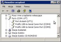
Najprostszą metodą sprawdzenia numeru portu przydzielonego do konwerter USB-RS232 jest wykonanie następujących czynności w komputerze:
- Odłączamy od komputera konwerter USB-RS232
- Klikamy prawym klawiszem myszy na ikonce Komputer(Mój komputer) i wybieramy opcje Właściwości
- Z otworzonego okienka wybieramy opcję: Menedżer urządzeń ( w Windows XP opcja ta znajduje się w zakładce Sprzęt)
- Na liście urządzeń rozwijamy pozycję Porty (COM i LPT)
- W tym momencie podłączamy konwerter USB-RS232 do komputera i czekamy aż na liście pojawi się nowe urządzenie USB Serial Port (COMxx)
- W nawiasie urządzenia będzie podany właściwy port COM.
- Jeżeli nie zdążyliśmy zaobserwować, które urządzenie się pojawiło, należy odłączyć konwerter i podłączyć ponownie.

Zdecydowanie tak. Cały czas rozwijamy oprogramowanie sterownika eCoal.pl/bruli.pl: udoskonalamy kod źródłowy, dodajemy nową funkcjonalność.
- komputer PC z systemem operacyjnym Windows
- port szeregowy w komputerze lub konwerter USB/RS232
- kabelek RS232 dostarczony wraz ze sterownikiem
- najnowsze oprogramowanie aktualizacyjne ściągnięte ze strony http://bruli.pl z zakładki Wsparcie: 6. Program aktualizacyjny
W pierwszej kolejności należy połączyć komputer ze sterownikiem kablem RS232:

Kabel RS232
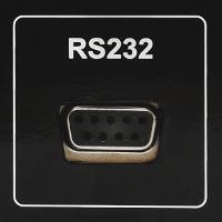
Złącze RS232 w sterowniku bruli.pl
Następnie należy uruchomić oprogramowanie aktualizacyjne:

Po uruchomieniu aplikacji należy wybrać port szeregowy RS232, do którego podłączony jest sterownik:
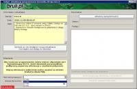
Po zestawieniu połączenia wystarczy kliknąć na przycisk: Aktualizuj oprogramowanie.
Następnie należy poczekać na zakończenie procesu aktualizacji oprogramowania.
W celu aktualizacji oprogramowania w sterowniku eCoal.pl będzie niezbędne:
- komputer PC z systemem operacyjnym Windows
- port szeregowy w komputerze lub konwerter USB/RS232
- kabelek RS232 dostarczony wraz ze sterownikiem
- najnowsze oprogramowanie aktualizacyjne ściągnięte ze strony http://eCoal.pl z zakładki Wsparcie: 4. Aktualizator sterownika
W pierwszej kolejności należy połączyć komputer ze sterownikiem kablem RS232:

Kabel RS232

Złącze RS232 w sterowniku eCoal.pl
Następnie należy uruchomić oprogramowanie aktualizacyjne: eCoalUpdater.pl_X.X.X.X.exe
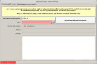
Aby rozpocząć aktualizację oprogramowania w sterowniku należy wybrać odpowiedni port komunikacyjny RS232, do którego podłączony jest sterownik. Jeżeli sterownik podłączony jest prawidłowo pojawi się informacja o uzyskaniu połączenia.
Po zestawieniu połączenia wystarczy kliknąć na przycisk: Aktualizuj oprogramowanie.
Następnie należy poczekać na zakończenie procesu aktualizacji oprogramowania.
Po aktualizacji oprogramowania w sterowniku należy zaktualizować stronę www.
Uruchamiamy to samo oprogramowanie, którym aktualizowaliśmy sterownik: eCoalUpdater.pl_X.X.X.X.exe i przełączamy się na zakładkę:Aktualizacja strony www.
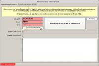
Podłączamy sterownik do lokalnej sieci Ethernet kabelkiem RJ45. Nadajemy sterownikowi niepowtarzalny adres IP, maskę oraz bramę (dokładny opis postępowania znajduje się w FAQ).
W programie aktualizacyjnym wypełniamy pole: Adres IP - wpisujemy adres IP sterownika. Podajemy login i hasło administratora (z prawami do zapisu) do strony www w sterowniku (domyślnie login: admin, hasło: admin). Klikamy na przycisk: Sprawdź połączenie.
Jeśli zostanie nawiązanie połączenie ze sterownikiem klikamy na przycisk: Aktualizuj stronę WWW w sterowniku.
Po zakończeniu aktualizacji możemy zamknąć program.
Pytania dotyczące obsługi sterownika ze strony WWW
Sterownik eCoal.pl/bruli.pl jest wyposażony w moduł z wyjściem Ethernet RJ-45. Sterownik posiada własny adres IP, dzięki czemu jest możliwość połączenia się z nim z każdego z komputerów w sieci lokalnej. Pomiędzy sterownikiem a siecią nie jest wymagany żaden konwerter, sterownik pracuje jako pełnoprawny komputer.
Sterownik pracuje jako serwer WWW - wystarczy wpisać w przeglądarkę adres IP sterownika a ujrzymy stronę główną - schemat instalacji c.o. Są dwa poziomy dostępu, pierwszy umożliwia jedynie odczyt parametrów, drugi zarówno odczyt jak i zapis. Istnieje możliwość sterowania podłączonymi urządzeniami, programatorami oraz przeglądanie archiwum w formie wykresów.
Preferowana przeglądarka internetowa to Google Chrome
Sterownik będzie działał prawidłowo również z przeglądarką Mozilla Firefox oraz Opera w wersji 10.60.
Przeglądarka Internet Explorer jest niezalecana, ze względu na nieobsługiwanie przez nią najnowszych standardów.
Sterownik podłącza się do sieci lokalnej tak samo jak dodatkowy komputer. Przewodem zakończonym z obu stron wtyczkami RJ45 podłączamy sterownik do wolnego gniazda w routerze lub switchu. Jeszcze jedną niezbędną czynnością jest ustawienie w sterowniku adresu IP, bramy oraz maski. Dostęp do internetu umożliwia uruchomienie usługi Zdalny dostęp.
Przygotowany specjalnie dla użytkowników sterownika eCoal.pl/bruli.pl portal umożliwiający Zdalny Dostęp do sterownika przez stronę www, w przypadku gdy nie posiadacie Państwo publicznego adresu IP. Serwer pośredniczący, umożliwia komunikację ze sterownikiem, który nie posiada publicznego adresu IP. Proszę kliknąć w zakładkę Zdalny Dostęp, zarejestrować się i dodać sterownik - wszystkie informacje są podane na stronie www.
Do podłączenia sterownika eCoal.pl/bruli.pl do modemu Livebox wymagane jest wyposażenie sterownika w moduł Ethernet oraz kartę SD. Podłączenie sterownika z modemem należy wykonać standardowym kablem PATCHCABLE CAT.5.
W sterowniku należy ustawić statyczny adres IP z puli adresów obsługiwanych w lokalnej sieci przez modem Livebox.
Aby sprawdzić działanie sterownika w lokalnej sieci komputerowej należy wpisać w przeglądarkę Firefox adres IP sterownika. Przy prawidłowym połączeniu i konfiguracji sieci przeglądarka poprosi podanie użytkownika i hasła do strony generowanej przez sterownik. Po podaniu użytkownika: admin oraz hasła: admin, pojawi się podgląd on-line pracującego kotła.
Aby była możliwość dostępu do sterownika z internetu, należy odpowiednio skonfigurować modem Livebox. W sieci jest wiele poradników, które precyzyjnie opisują cały proces postępowania. Dla przykładu podajemy jeden z nich: kliknij tutaj
Przygotowany specjalnie dla użytkowników sterownika eCoal.pl/bruli.pl portal umożliwiający Zdalny Dostęp do sterownika przez stronę www, w przypadku gdy nie posiadacie Państwo publicznego adresu IP. Serwer pośredniczący, umożliwia komunikację ze sterownikiem, który nie posiada publicznego adresu IP. Proszę kliknąć w zakładkę Zdalny Dostęp, zarejestrować się i dodać sterownik - wszystkie informacje są podane na stronie www.
Aby powiększyć wykres należy zaznaczyć na wykresie od lewej do prawej strony obszar, który jest częścią wykresu którą chcemy powiększyć.
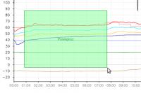
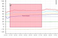
Następnie aby pomniejszyć wykres do stanu początkowego należy zaznaczyć dowolny obszar od prawej do lewej strony:
Usługa "Zdalny dostęp" na stronie eSterownik.pl jest przeznaczona do podglądu i zmiany parametrów w sterowniku przez Internet.
Przygotowany specjalnie dla użytkowników sterownika eCoal.pl/bruli.pl portal umożliwiający Zdalny Dostęp do sterownika przez stronę www, w przypadku gdy nie posiadacie Państwo publicznego adresu IP. Serwer pośredniczący, umożliwia komunikację ze sterownikiem, który nie posiada publicznego adresu IP. Proszę kliknąć w zakładkę Zdalny Dostęp, zarejestrować się i dodać sterownik - wszystkie informacje są podane na stronie www.
Zdalny dostęp jest przydatny w następujących sytuacjach:
1. Chcemy mieć dostęp do kotła w przypadku gdy przebywamy poza miejscem zamieszkania. Dzięki temu mając dostęp do internetu możemy ustawić np. temperaturę w mieszkaniu po naszym powrocie.
2. Chcemy podzielić się uwagami ze znajomym. Możemy udostępnić mu sterownik kotła z prawami tylko do odczytu.
3. Kocioł pracuje nieprawidłowo i chcemy zasięgnąć opinii serwisu - udostępniamy sterownik serwisowi a ten przez internet analizuje pracę kotła.
4. Udostępniamy sterownik publicznie - dzięki temu każdy internauta które wejdzie na stronę eSterownik.pl może podejrzeć jak pracuje nasz kocioł. Oczywiście posiada prawa tylko do odczytu.
1.W komputerze z systemem Windows klikamy na Start, następnie Uruchom
2.Wpisujemy cmd i klikamy OK
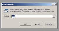
3.Otwiera się okno z konsolą
4.Wpisujemy ipconfig i naciskamy klawisz Enter
Potrzebne dane są zaznaczone w kółku:
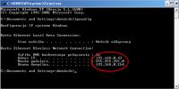
5.W sterowniku należy ustawić identyczną bramę oraz maskę, adres IP musi być inny.
Zmieniamy ostatnią liczbę adresu IP na dowolną inną, w powyższym przykładzie będzie to np. 192.168.0.69
6.Sprawdzamy czy adres IP nie jest już zajęty:
Wpisujemy ping 192.168.0.69 i naciskamy klawisz Enter
Jeśli otrzymamy podobny komunikat:

musimy wybrać inny adres IP i powrócić do punktu 6, jeśli komunikat będzie następujący:

możemy sądzić, że wybrany adres IP nie jest przydzielony żadnemu komputerowi lub innemu urządzeniu i możemy go przypisać do naszego sterownika - przechodzimy dalej.
7.Ustawiamy w sterowniku bramę, maskę odczytane uprzednio z konsoli oraz wybrany wolny adres IP.
W tym celu w panelu operatorskim wchodzimy w menu Internet:
- przytrzymujemy klawisz OK
- przyciskami w górę i w dół wybieramy Internet i naciskamy OK
- wpisujemy Adres IP, Brama oraz Maska
8.Podłączamy sterownik kablem typu skrętka zakończony wtykiem RJ45, z naszą siecią lokalną (router, switch itp):
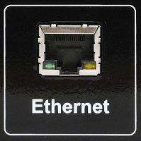
9.Sterownik powinien się automatycznie połączyć z siecią. Możemy to sprawdzić logując się do Panelu WWW w sterowniku eCoal.pl/bruli.pl. W tym celu wpisujemy w przeglądarce internetowej adres IP sterownika który ustawiliśmy (w naszym przykładzie): http://192.168.0.69
10. Logujemy się do panelu WWW podając login i hasło (domyślnie: admin, admin). Jeśli wyświetli się poniższe okno logowania, oznacza to iż ustawiliśmy parametry sieci w sterowniku poprawnie.

Usługa Zdalny dostęp jest adresowana dla osób, które zakupiły sterownik i chcą mieć bezproblemowy dostęp do parametrów kotła przez internet. Konfiguracja usługi jest prosta i nie wymaga doświadczenia.
Usługa została stworzona po to, aby ominąć takie problemy jak:
- brak publicznego adresu IP (użytkownicy sieci komórkowych, kablowych itp.)
- brak stałego adresu IP (użytkownicy internetu ADSL np. Neostrada)
- trudności w konfiguracji routerów
Korzystanie z usługi jest darmowe.
1.Pierwszym krokiem który musimy wykonać jest rejestracja na stronie https://eSterownik.pl W tym celu klikamy Zarejestruj się.
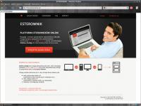
2.Po rejestracji logujemy się na stronie i przechodzimy do zakładki Zdalny dostęp i klikamy Dodaj nowy sterownik
3.W tym momencie powinniśmy mieć skonfigurowane połączenie ze sterownikiem z sieci lokalnej. Jeśli tak nie jest przechodzimy do odpowiedniego miejsca w instrukcji. Jeśli mamy już dostęp do strony w sterowniku klikamy Dalej.
4.Dane podstawowe

- Nazwa – dowolna nazwa sterownika, będzie wyświetlana jako nazwa identyfikująca dany sterownik
- Udostępnij sterownik publicznie – sterownik zostanie udostępniony na stronie eSterownik.pl dla każdego odwiedzającego, jednak jedynie do podglądu (tylko użytkownik będzie mógł zmieniać parametry sterownika)
- Włącz powiadamianie na email – włącza opcję przesyłania wiadomości z alarmami na email. Email do powiadamiania – na podany email przy rejestracji konta będą wysyłane powiadomienia oraz wiadomości od administratora
- Synchronizacja czasu przez internet – jeśli ta opcja jest zaznaczona w sterowniku będzie automatycznie synchronizowany czas z zegarem serwera
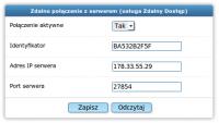
5.Dane do wpisania w sterowniku:

- Identyfikator - Niepowtarzalny identyfikator sterownika
- Adres IP serwera - Adres IP serwera pośredniczącego
- Port serwera - Port serwera pośredniczącego
6.W tym momencie możemy ustawić poprzez Panel WWW sterownika powyższe dane. Przechodzimy do panelu www wpisując w przeglądarce adres IP sterownika oraz login i hasło administratora (domyślenie admin, admin). Następnie przechodzimy do zakładki Ustawienia->Internet -> Zdalne połączenie z serwerem i przepisujemy Identyfikator, Adres IP serwera oraz Port serwera podane w poprzednim oknie Zdalnego dostępu:
7.Klikamy Zapisz
Dane te możemy ustawić również poprzez Panel operatorski, w tym celu:
- przytrzymujemy klawisz OK
- przyciskami w górę i w dół wybieramy Internet i naciskamy OK
- wpisujemy wszystkie powyższe dane za pośrednictwem panela operatorskiego
8.Zachęcamy do wypełnienia pozostałych pól formularza – Miejsce instalacji oraz Dane dodatkowe.
9.Klikamy Dalej aby przejść do kolejnego kroku - pojawi się następujący komunikat:
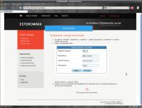
Łączenie ze sterownikiem może potrwać od 5 do 60 sekund. Po ustanowieniu połączenia pojawi się niebieska ikona przy sterowniku na liście Twoje sterowniki:

W przypadku gdyby sterownik nie chciał się połączyć, należy sprawdzić jego połączenie z siecią lokalną (polecenie ping lub zalogowanie się lokalnie przez przeglądarkę internetową) oraz połączenie sieci z internetem. Należy również sprawdzić poprawność wprowadzonych danych w sterowniku.
Ta opcja pozwala udostępnić innemu użytkownikowi własny sterownik. Dzięki temu możemy udostępnić sterowanie swojemu znajomemu lub na przykład udostępnić sterownik tylko do odczytu serwisowi który instalował nam kocioł. Może to być pomocne w wyjaśnieniu ewentualnych problemów z kotłem. Serwis może przeglądać archiwalne dane pracy kotła.
1.Logujemy się w serwisie eSterownik.pl
2.Wchodzimy w zakładkę Zdalny dostęp -> Twoje sterowniki
3.Klikamy na wybrany sterownik na liście
4.Klikamy Udostępnij
5.Pojawia się okno:
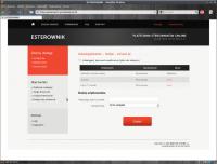
6.W polu Dodaj użytkownika wpisujemy login lub email użytkownika, któremu chcemy udostępnić sterownik. Wybieramy dla niego uprawnienia:
- Tylko podgląd – umożliwia jedynie odczyt parametrów, użytkownik nie ma możliwości zmiany żadnego parametru, czy tez sterowania
- Pełne prawa – odczyt i zapis parametrów, użytkownik może sterować naszym kotłem i modyfikować wszystkie parametry sterownika.
7.Użytkownik, któremu nadaliśmy prawa znajdzie sterownik w zakładce Twoje sterowniki